Sizing a sewage pump system involves a systematic evaluation of hydraulics, solids-handling needs, controls and basin requirements. Below are the core data points and calculation steps, followed by how Triple D Pump integrates them into turnkey lift-station solutions.
Key Information Required for Sizing a Sewage Pump System
- Peak and average flow rate (GPM)
- Vertical lift (static head) and system back-pressure
- Friction losses in the discharge piping (length, diameter, fittings)
- Solids-handling requirement (size of spherical solids to be passed)
- Electrical supply (voltage, phase) and control preferences
- Basin volume, on/off differential and simplex vs. duplex configuration
1. Determine Design Flow (Pump Capacity)
To size for flow, the industry’s most practical approach is the Fixture Unit method:
- List all plumbing fixtures discharging into the pump sump.
- Assign each fixture a “fixture unit” value (e.g., a water closet = 6 FU, a kitchen sink w/ disposal = 3 FU).
- Sum the fixture units and use a published chart (Fixture Units vs. GPM) to find the design flow in gallons per minute.
2. Calculate Total Dynamic Head (TDH)
TDH combines:
- Static head: vertical distance from the minimum water level in the basin to the highest discharge point.
- Friction head: resistance in piping and fittings, expressed as equivalent feet per 100 ft of pipe.
- Any system back-pressure (e.g., a pressurized force main, converted from PSI to feet using 1 PSI = 2.31 ft).
Steps:
- Measure static head.
- Tally each fitting’s equivalent length, add to actual pipe length, then multiply by the friction factor at the design flow rate.
- Sum static head + friction head (+ back-pressure head) to get TDH.
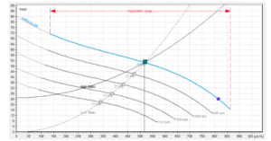
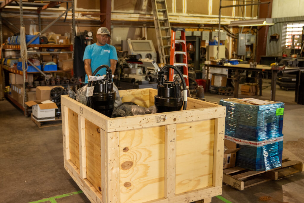
3. Select Pump and Impeller Type
With design flow (GPM) and TDH plotted as a point on manufacturer pump curves:
- Choose a pump whose performance curve passes at or just above that point.
- Aim for the middle of the curve for best efficiency and longer run times (avoiding short-cycling).
- Confirm the impeller style (semi-open, vortex or cutter/grinder) matches your solids-handling requirement (minimum 2 in. sphere for typical sewage).
4. Size Basin & Controls
- Basin volume should provide enough drawdown to avoid rapid cycling—typically 3–4× the pump capacity per cycle.
- Determine simplex versus duplex based on redundancy needs and local code.
- Specify float switch on/off differentials, alarm floats and control panel features to match system criticality.
Triple D Pump’s Sizing & Selection Process
Triple D Pump delivers fully designed and engineered lift stations by gathering:
- Peak design flow (GPM)
- Force-main data: length (ft), diameter (in.) and material
- Elevation difference (static head) and any back-pressure requirement
- Sewage inflow depth (ft) into the basin
- Solids handling, voltage/phase and desired controls (simplex/duplex, alarms)
Their in-house team then:
- Run hydraulic calculations to confirm TDH and minimum scouring velocity.
- Select compatible pumps and impellers from trusted OEMs.
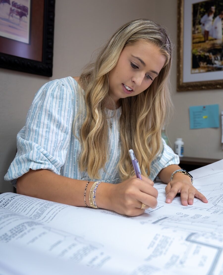
- Lay out guide-rail systems, valves, float arrays and control panels in CAD.
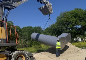
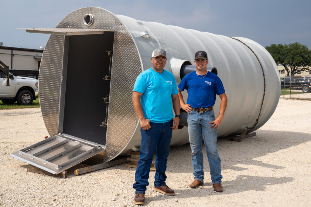
- Package everything into a drop-in station, complete with test reports and on-site startup support.
By tailoring each system to your site parameters, Triple D ensures optimal performance, reliable solids handling and streamlined installation. Check out our Youtube Channel and our services page to learn more about what we provide and how we go above and beyond for our customers.
Ready to size your next sewage lift station? Reach out to Triple D Pump for a custom quote and full application support.